A Component Based Architecture for
CAN Based Systems
Dean Gifford, Brian Kirk & Bernhard Leisch
Abstract:
This paper describes a general purpose architecture for designing distributed real time control systems based on component oriented system decomposition and CAN based communications.
The basic philosophy of the architecture is to use an object – oriented analysis approach to partition the control system into logical subsystems, each of which is built from a set of co-operating software components.
A CAN message distribution layer provides a transport service for messages sent between components, thus components can communicate in the same way whether they are on the same node or on different nodes. This ‘virtual CAN bus’ approach requires only a single CAN channel in the hardware chip.
As a result highly scalable systems can be developed, with variants of a product family being built from a common set of software components using a database to define the configuration. Legacy systems can be integrated using components which act as agents.
A generic solution to the CAN duplicate message reception problem is presented using this design.
Keywords:
CAN, component communication, location independent message transport, duplicate message filtering, agent.
Introduction
This paper describes a software architecture for distributed control systems using CAN networked software components The objective has been to find a practical design with as little system overhead as possible while still giving enough flexibility to be able to solve real-world problems. A lot of consideration has been given to the problems encountered when enabling control system software reuse in similar projects, for example to support a range of machines providing a scalable solution for customers. Different models might be distinguished by offering different throughput, either by using faster and more expensive devices or by using several devices in parallel. A more complex machine might employ both techniques along the production line. In all of these cases the actual hardware configuration varies, but the fundamental control problems change very little.
An approach for designing distributed real time CAN based systems using a general purpose architecture has already been discussed in [DART]. That control system design model has been used as a basis, and then enhanced to follow a rigorous system decomposition into components. The components are then used as the basic building blocks of a configurable control system. Unlike most of the prevalent component architectures we have chosen a lean component model that seems more appropriate for a real time control system, while preserving many of the fundamental ideas found in standard component models [Harm].
Special attention has also been paid to the underlying communications architecture, which is called MANTRA (Message Agent for Network TRAnsport). MANTRA is a logical extension of the physical CAN bus and provides for location independent messaging between components, based on the ISO Open Systems Interconnect reference model.
System Architecture
Much has already been written about system architectures based on components [Jacobson, UML] however the additional design constraints of having a physically modular scalable real-time product, involving much component reuse, meant that a new approach was needed [DART].
- Subsystems
The system is partitioned into a series of logical subsystems each with a clearly defined purpose, see Figure 1.
Subsystems are entirely abstract entities which aid the process of finding a suitable breakdown of the system into smaller sub-problems during the design phase. The notion of a subsystem with a well defined purpose and interface to other parts of the system greatly benefits the task of finding a proper abstraction of the problem domain.
An example for a subsystem might be the engine in a car, where the subsystem is more tangible as it has a well defined physical representation. On the other hand a subsystem might also be a product tracking system which maintains the information on the location of product assemblies currently going through the production line. In this case the subsystem is the representation of a concept, and the physical implementation is distributed and spans the entire production line.
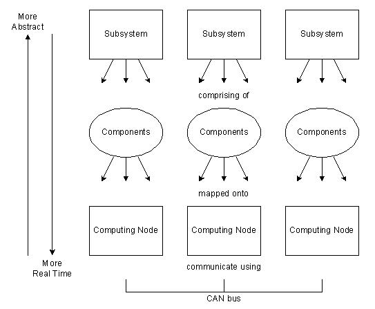
Figure 1
- Components
Each subsystem is partitioned into one or more components. A component is defined as an independent event driven software object which communicates with other objects via messages. The interface of an object is defined by the set of messages it expects to receive and by the set of messages it is able to send. Its behavior is defined in terms of its response to incoming event messages, its local interaction with input – output devices and the messages it sends as requests and responses to other components. A component is a single software entity that is executed on one processing node, a single instance of a component can not be executed in a distributed fashion where parts of the component are executed on different nodes. A single component may however use several tasks, although this complexity is avoided wherever possible.
Ideally the entire external interface of a component should be CAN message based, making it possible to trace all message activity between components at the system level. Communication within a node consisting of several tasks is only procedure call based when timing or bandwidth requirements do not permit the usage of CAN messages.
Components are launched by a task manager (see Figure 2) on system start up.
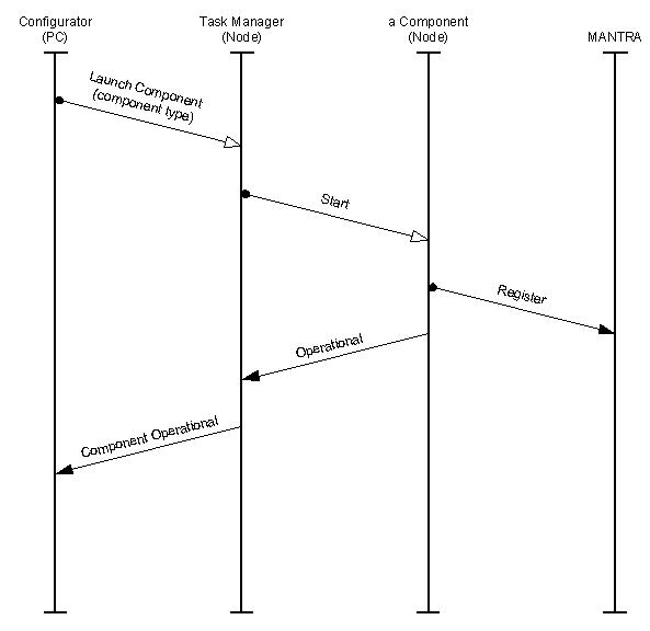
Figure 2
Two mechanisms for system wide component start up can be used to match different levels of configuration needs:
1. Each node contains the executable code of all components. Only one executable image is required throughout the system, which simplifies maintenance and configuration issues. The task managers link between activation protocol and launching components can be hard coded.
2. Each node contains only a subset of the components. Several different executable images need to be generated and maintained. Each node is specialized on specific tasks, depending on which components have been compiled into its image. During system initialization all component class implementations register with the task manager, each presenting a pair of unique class ID and instantiation function. GUIDs (Globally Unique IDentifier) have deliberately not been used, because the control system does not support the concept of persistent component representation. Therefore the problems introduced when the life span of a components representation as data exceeds the life span of the code it is associated with are not encountered.
Node Software
The software on each node consists of a fixed part, the node infrastructure, and a variable part i.e. the components which belong to various subsystems.
The node infrastructure consists of the operating system, input – output device drivers, a task manager and MANTRA. This framework of system components is present on all nodes.
The kind and number of application components present in a node depend on the specific control system entirely.
System Configuration
The number and kind of physical devices present in an actual machine depends on the configuration of the machine. The number of nodes present may also vary.
To simplify configuration issues as well as parts and spares management the architecture has been oriented towards a control system implementation using physically identical processing nodes. However there is no system inherent limitation preventing the use of the system architecture on a heterogeneous system.
The system architecture is designed to cope with varying configuration scenarios without requiring the re-compilation of any part of the control system software.
The whole system configuration is stored in a database that is located on a PC, which is connected to the control system (see Figure 3). At system start-up time the system configurator on the database PC downloads the system configuration into the control system.
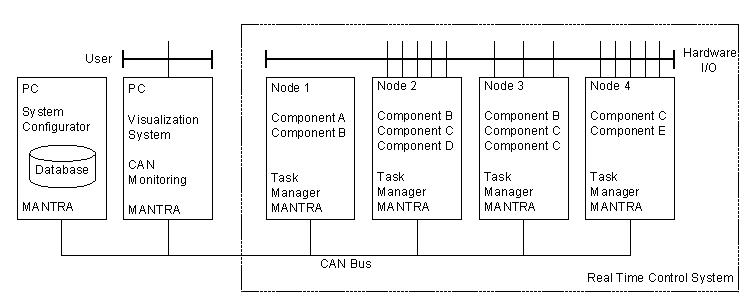
Figure 3
The only active component in each control node after power-up is the task manager. During the first stage of system configuration it is used to launch the components required to run on each individual node by binding them to tasks. Each component then runs and registers with MANTRA to inform it of the set of messages it expects to receive. Once this has been completed, each node exhibits different behaviour that is specific to its purpose in its subsystem (see components shown to be active in the nodes in Figure 3).
Requirements for Messaging Between Components
In order to provide flexibility in allocating software components to CAN nodes it is necessary to provide a means for location independent messaging between components. The requirements are
- communicating components may be on the same nodes or different nodes
- components sending messages are unaware of the identity of the nodes which contain the components which receive the messages
- the distribution of messages to components must be completely transparent to the components
- components should only receive messages within their expected set (otherwise their error handling has to cope with an unknown set of messages)
- it must be possible to monitor inter-component messages within a node
- the message distribution mechanism should be independent of the CAN chip and its device driver
- as few physical CAN channels as possible should be used
- it should be possible to filter out rogue duplicate messages sent as a result of physical packet corruption on the CAN bus.
The lifecycles of the components and the interactions between them were designed and documented using the UML Jacobson diagrams [Jacobson].
The MANTRA Design
It is highly desirable to allocate software components to nodes which are physically near to the devices they control in order to reduce wiring. This means that messages between components need to be routed between the nodes which happen to be hosting the communicating components.
The problem of distributing messages transparently between nodes has been solved by using a software agent called MANTRA (Message Agent for Network TRAnsport). This is itself a software component which exists on each node in the system.
It is designed to offer a single point of access to the network for application components, based on a safe connectionless datagram network service. The design is based on earlier work [Mühl-Esch, Lei-Schuh], where a similar message oriented communication layer provided services in the context of an object – oriented system. The design of MANTRA is more streamlined in comparison, as the CAN bus already provides a reliable but connectionless datagram network service.
The design of MANTRA is shown in Figure 4. It has been inspired by the ISO OSI Reference Model. Deviations from the standard are caused mainly by the desire to preserve the unique features of the CAN protocol up to the level of the application layer, and real time response.
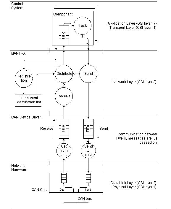
Figure 4
MANTRA has four levels of activity, which are from the bottom up
- Physical and Data Link Layer
The CAN bus and chips deliver all messages to all nodes
- CAN Device Driver
The CAN driver catches incoming messages and stores them in a receive FIFO buffer for later use. It also takes messages from a send FIFO buffer and transmits them via the CAN chip. In our case this CAN driver is interrupt driven to guarantee that incoming messages are never lost.
The message handling on each level is executed concurrently to the handling on the other levels. Therefore the FIFOs forming the interface between layers use protected access mechanisms.
- Network Layer
The MANTRA layer provides a logical connectivity layer which spans all nodes. Within a node at initialization time each component registers with MANTRA and informs it of all the CAN Objects (COBs) it expects to receive [Mühl-Esch]. These are stored in a list which is designed for rapid read access.
MANTRA takes received CAN messages from the driver, looks up which set of components need to receive it (possibly none). It then copies the message into each components incoming message buffer on an as needed basis.
- Transport and Application Layer
Each component has its own message-event driven lifecycle and so simply removes messages from its own input queue and processes them. A nice feature of MANTRA is that each component only receives the set of messages it expects i.e. those it has pre-registered for. In our experience this makes the design of each component independent of other ones. It also makes the error handling and testing simpler.
For the sake of efficiency the message service provided to components maps one to one to CAN messages. In fact most messages fit naturally within the maximum CAN message length. However, if a component needs to send or receive a large block of data, it has to perform the operation of splitting up the data into messages or the reassembly of messages into contiguous data itself. Therefore conceptually the OSI Transport Layer also resides within the component level.
With this design it now becomes possible to allocate components to nodes which have spare computing capacity and/or spare input/output hardware interfaces. A scheme for providing a generic configurable hardware interface driver has also been designed so that component software can be designed independently of the physical hardware interface node location. This provides flexibility in moving a component and its hardware I/O driver from one node to another to balance resource allocation between the nodes.
The CAN Message Duplication Problem
Control systems which use a high integrity field bus are generally designed to depend on its reliability. Unfortunately the design of the CAN bus has an inherent problem: under certain circumstances a message which has been sent only once by the software might be received twice by all receivers [CanFAQ]. This has been the source of some concern in the industry.
On each node MANTRA provides a single consistent point of access to the CAN bus for all other components of the control system. Message handling within MANTRA (see Figure 4) can be enhanced to provide a generic solution to the double message reception problem using the following mechanism:
If all messages in the control system use a layout where the first byte of the message is a message multiplexor, then by limiting the multiplexor range to 0..127 per COB one bit in the multiplexor can be reserved to be used as a toggle bit. MANTRA maintains the toggle bit itself, and hides the mechanism from the clients. MANTRA automatically toggles the bit after each message sent on the same COB. Therefore by definition there cannot be two consecutive valid messages with the same value in the multiplexor byte. If such a pair of messages is received, the second message can be discarded safely, thus eliminating the effects of the double message reception problem on all higher software levels.
The situation is slightly more complex if
- hardware filtering is used based on the current clients COB registrations and
- the clients are allowed to dynamically change COB registrations at run-time.
The main benefit is that duplicate messages can be discarded by MANTRA, and no code is required in other components to deal with this problem.
This mechanism is optional and can be deployed depending on the reliability of the physical bus implementation.
Providing Accurate Event Timing
Various schemes have been put forward for providing a system wide synchronous clock across all nodes [Kiencke, Rau Weh, Turski]. In order to achieve the highest system wide precision, node can be synchronised by a single wire which interrupts them all simultaneously. It would however be easy to extend the CAN driver to timestamp the arrival time of all messages and store this in the receive buffer if it were needed.
The approach we have taken for event timing is for the source of a time critical event to timestamp its occurrence and to send this as part of the content of the message. This has the great advantage that various latency and jitter delays in the CAN bus, CAN chips, CAN drivers and MANTRA do not affect the absolute timing of the knowledge of the event’s occurrence. This can greatly simplify many calculations and greatly improve the accuracy of the absolute timing throughout the system.
Practical Considerations
The initial version of MANTRA has high and low watermarks on the various queues in the system, which has enabled the profiling of buffer loading and hence provide buffers of reasonable but safe size. In practice the queues contain only one message unless there is a prolonged full bandwidth burst of messages with 3 or 2 data bytes i.e. the worst case loading scenario.
An idle task is used to monitor spare CPU bandwidth and this also confirms that the message handling overhead is acceptable except in the case already mentioned.
In practice all the benefits of the clean message distribution abstraction have been gained with all components written in a high level language. No handcrafting of coding has been necessary.
Conclusions
The use of MANTRA has made it possible to partition the system into subsystems and then into components and to allocate them to computing nodes in a flexible way. This is of great advantage for the parallel development of numerous components by larger teams. It also supports the separation of specification, design, programming and testing of each component.
The flexibility resulting from designing separate components and being able to allocate them to nodes at system initialisation time simplifies the production of scalable products and their variants without programming changes.
Thanks to careful design using Jacobson diagrams there are very few problems when new components are integrated into the system. All this flexibility has been gained without loosing the deterministic timing character of the CAN bus.
Acknowledgements
We would like to thank Libero Nigro from the Universita’ Della Calabria, Italy and Peter Dietmüller from the Johannes Kepler Universität Linz, Austria for contributing time in many inspiring discussions on the subject.
References
[CanFAQ]
CAN Frequently Asked Questions
http://www.nrtt.demon.co.uk/
canfaq.html
[CiA]
CAN Application Layer
CiA/DS201 … DS205, DS207
CiA, D-90427, Nurenberg
[Harm]
Components
Paul Harmon
Component Development Strategies, Volume VIII, No.7; July 1998
Cutter Information Corp. 1998
[Jacobson]
Object-Oriented Software Engineering
I Jacobson, M Christerson, P Jonsson, G. Övergaard
Addison-Wesley 1994
ISBN 0-201-54435-0
[Kiencke]
Controller Area Network – from Concept to Reality
U Kiencke
Proceedings 1st International CAN Conference
Pages 0-11 to 0-20
[Kirk – Nigro]
A Distributed Architecture for Real Time
B Kirk, L Nigro
Joint Modular Languages Conference, 1994, Ulm
ISBN 3-89559-22--X
[KNP]
Using Real Time Constraints for Modularisation
B Kirk, L Nigro, F Pupo
Lecture Notes in Computer Science 1204
Modular Programming Languages, JMLC 1997
Springer ISBN 0302-9743
[Lei – Schuh]
An architecture for distributed visualization of technical processes
B Leisch, P Schuhmayer
Journal of Network and Computer Applications 20
Academic Press 1997
[Mühl – Esch]
A Framework of Classes for Distributed Controlling
J. R. Mühlbacher, G. Eschelbeck
Proceedings Euromicro Conference Liverpool
Pages 240-246
IEEE Computer Society Press
[UML]
Applying UML and Patterns: An Introduction to Object-Oriented Analysis and Design
Craig Larman
Prentice Hall 1997
ISBN 0-13-748880-7
[Rau Weh]
Synchronous Processes with CAN Higher Layer Implementations
L Rauchhaupt, S Wehmann
Proceedings 4th International CAN Conference
[Turski]
A Global Time System for CAN Networks
K Turski (NEC chip specific)
Proceedings 1st International CAN Conference
Pages 3-2 to 3-7
|
Robinson Associates
Red Lion House
St Mary’s Street
Painswick, Glos.
GL6 6QG
United Kingdom
Tel: +44 (0)1452 813699
Fax: +44 (0)1452 812912
Email: enquiries@robinsons.co.uk
Homepage: www.robinsons.co.uk |
FIM
Institute for Information Processing and Microprocessor Technology
Johannes Kepler Universität
Altenberger Straße 69
A-4040 Linz
Austria
Tel: +43 (0)732 2468 440
Fax: +43 (0)732 2468 599
Email: leisch@fim.uni-linz.ac.at
Homepage: www.fim.uni-linz.ac.at |